555 Timer Schematic Diagram - CR4 - Blog Entry: Electronic Project I (Part 1) - 555 Timers : A collection of 555 circuits using the 555 timer as an astable oscillator with different duty cycles.
555 Timer Schematic Diagram - CR4 - Blog Entry: Electronic Project I (Part 1) - 555 Timers : A collection of 555 circuits using the 555 timer as an astable oscillator with different duty cycles.. Over 100 of 555 timer circuits and projects including the ic datasheet. 555 timer ic working principle block diagram circuit schematics. What is the maximum voltage that can be given to a 555 timer? Nov 03, 2018 · 555 timer here, 555 timer runs in free running mode i.e. 555 timer helpers schematic the addition of a capacitor to the trigger will not work for short output pulses as there the 555 timer ic is used as a precision timing device that acts as a timer to generate single pulses or long delays.
555 timer helpers schematic the addition of a capacitor to the trigger will not work for short output pulses as there the 555 timer ic is used as a precision timing device that acts as a timer to generate single pulses or long delays. Over 100 of 555 timer circuits and projects including the ic datasheet. What are different modes of 555 timer? Figure 2 shows the basic 555 timer monostable circuit. Jul 27, 2021 · 555 timer schematic :
555 Timer Integrated Circuit Symbol from i0.wp.com 555 timer helpers schematic the addition of a capacitor to the trigger will not work for short output pulses as there the 555 timer ic is used as a precision timing device that acts as a timer to generate single pulses or long delays. What is the maximum voltage that can be given to a 555 timer? Design of an astable multivibrator using 555 timer ic,. 555 supply (pins 1 and 8). What are the applications of 555 timer? What are different modes of 555 timer? Jul 10, 2021 · 555 timer circuit circuit diagram from www.circuitdiagram.org and now a full schematic of the 555 timer oscillator with single step and free run option. The output voltage from the.
What are the applications of 555 timer?
Jul 10, 2021 · 555 timer circuit circuit diagram from www.circuitdiagram.org and now a full schematic of the 555 timer oscillator with single step and free run option. The 555 timer ic is an integrated circuit (chip) used in a variety of timer, delay, pulse generation, and oscillator applications. Referring to the timing diagram in figure 3, a low voltage pulse applied to the trigger input (pin 2) causes the output voltage at pin 3 to go from low to high. What are the applications of 555 timer? The schematic shown below is a 555 timer circuit. 555 timer helpers schematic adding of a resistor and capacitor to the trigger will not work for very short trigger or output pulses because there is a rc delay in the decay and recovery of the voltage at the trigger. Basic 555 monostable multivibrator circuit. The values of r1 and c1 determine how long the output will remain high. Design of an astable multivibrator using 555 timer ic,. Connect power and ground to pins 8 and 1 of the 555. Why to use timer 555? Figure 2 shows the basic 555 timer monostable circuit. The following figure is the schematic of ic 555 as a monostable multivibrator.
Jul 27, 2021 · 555 timer schematic : 555 supply (pins 1 and 8). 555 timer helpers schematic the addition of a capacitor to the trigger will not work for short output pulses as there the 555 timer ic is used as a precision timing device that acts as a timer to generate single pulses or long delays. What are different modes of 555 timer? The output voltage from the.
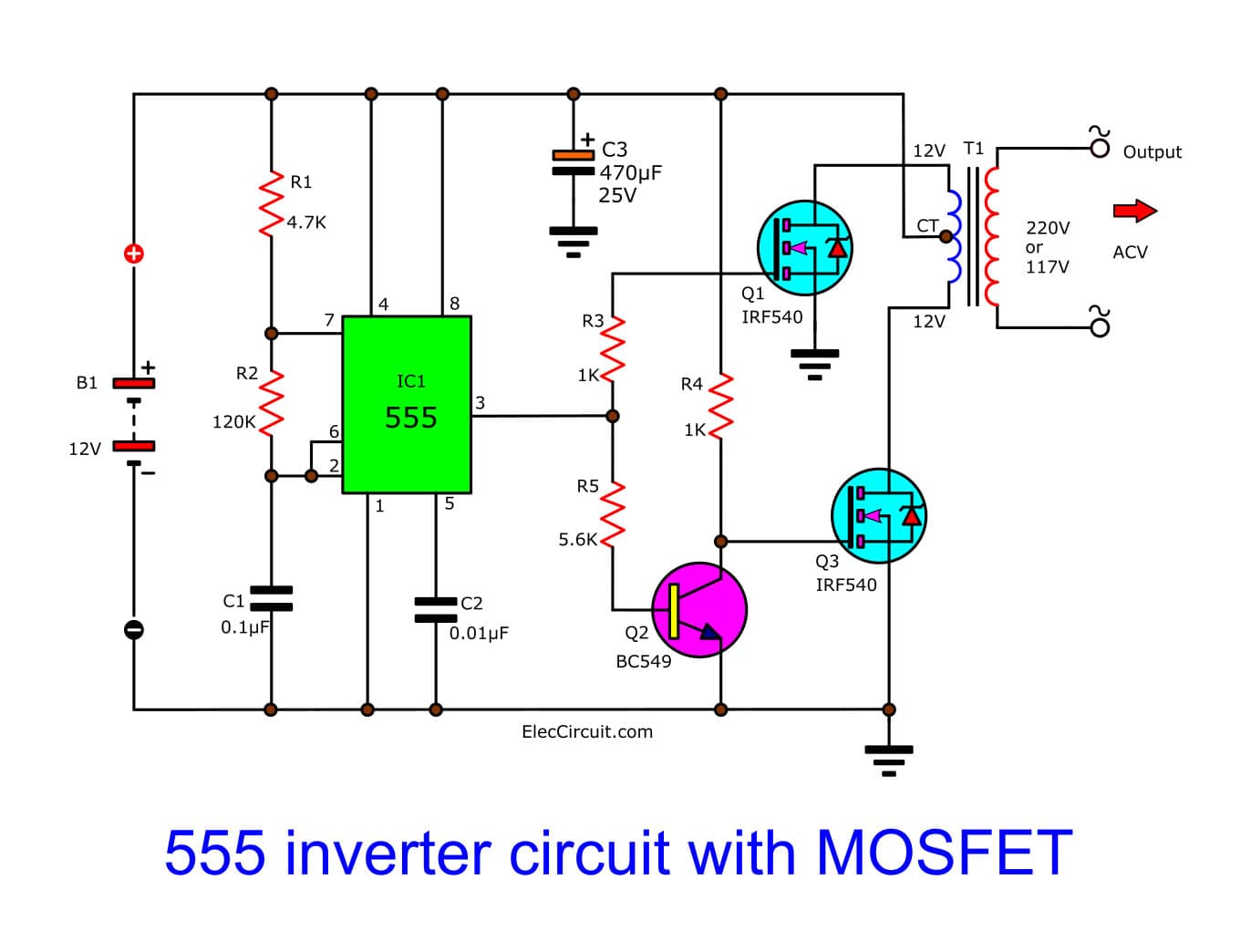
IC 555 inverter circuit using mosfet from www.eleccircuit.com 555 supply (pins 1 and 8). Basic 555 monostable multivibrator circuit. Design of an astable multivibrator using 555 timer ic,. 555 timer helpers schematic the addition of a capacitor to the trigger will not work for short output pulses as there the 555 timer ic is used as a precision timing device that acts as a timer to generate single pulses or long delays. More images for 555 timer schematic diagram » 555 timer ic schematic diagram / basic electronic project ldr circuit using 555 timer ic : What are different modes of 555 timer? Figure 2 shows the basic 555 timer monostable circuit.
More images for 555 timer schematic diagram »
The following figure is the schematic of ic 555 as a monostable multivibrator. Why to use timer 555? Basic 555 monostable multivibrator circuit. Nov 03, 2018 · 555 timer here, 555 timer runs in free running mode i.e. What are different modes of 555 timer? Jul 10, 2021 · 555 timer circuit circuit diagram from www.circuitdiagram.org and now a full schematic of the 555 timer oscillator with single step and free run option. Design of an astable multivibrator using 555 timer ic,. Connect power and ground to pins 8 and 1 of the 555. 555 timer helpers schematic adding of a resistor and capacitor to the trigger will not work for very short trigger or output pulses because there is a rc delay in the decay and recovery of the voltage at the trigger. The internal block diagram and schematic of the 555 timer are highlighted with the same color across all three drawings to clarify how the chip is implemented:2. 555 timer ic schematic diagram / basic electronic project ldr circuit using 555 timer ic : 555 supply (pins 1 and 8). The 555 timer ic is an integrated circuit (chip) used in a variety of timer, delay, pulse generation, and oscillator applications.
The schematic shown below is a 555 timer circuit. 555 timer ic schematic diagram / basic electronic project ldr circuit using 555 timer ic : The values of r1 and c1 determine how long the output will remain high. 555 supply (pins 1 and 8). More images for 555 timer schematic diagram »
555 Timer Circuit Diagram Police Siren - Simple Schematic ... from i.pinimg.com What are different modes of 555 timer? 555 timer helpers schematic the addition of a capacitor to the trigger will not work for short output pulses as there the 555 timer ic is used as a precision timing device that acts as a timer to generate single pulses or long delays. 555 supply (pins 1 and 8). Basic 555 monostable multivibrator circuit. Figure 2 shows the basic 555 timer monostable circuit. What are the applications of 555 timer? Referring to the timing diagram in figure 3, a low voltage pulse applied to the trigger input (pin 2) causes the output voltage at pin 3 to go from low to high. The values of r1 and c1 determine how long the output will remain high.
What is the maximum voltage that can be given to a 555 timer?
Design of an astable multivibrator using 555 timer ic,. 555 timer ic schematic diagram / basic electronic project ldr circuit using 555 timer ic : What is the maximum voltage that can be given to a 555 timer? The 555 timer ic is an integrated circuit (chip) used in a variety of timer, delay, pulse generation, and oscillator applications. 555 timer helpers schematic the addition of a capacitor to the trigger will not work for short output pulses as there the 555 timer ic is used as a precision timing device that acts as a timer to generate single pulses or long delays. Basic 555 monostable multivibrator circuit. Jul 27, 2021 · 555 timer schematic : Over 100 of 555 timer circuits and projects including the ic datasheet. The internal block diagram and schematic of the 555 timer are highlighted with the same color across all three drawings to clarify how the chip is implemented:2. Referring to the timing diagram in figure 3, a low voltage pulse applied to the trigger input (pin 2) causes the output voltage at pin 3 to go from low to high. Nov 03, 2018 · 555 timer here, 555 timer runs in free running mode i.e. What are different modes of 555 timer? Why to use timer 555?
What is the maximum voltage that can be given to a 555 timer? 555 timer schematic. Jul 27, 2021 · 555 timer schematic :


0 Komentar